Table of Contents:
What Are Reflective Markers?
Why Are Reflective Markers Needed in 3D Scanning?
Reflective Markers Placement Guidance
How Can ZG 3D Laser Scanner Help Quality Inspection When Scanning with Markers?
Marker-Free Solutions
The Conclusion
1. What Are Reflective Markers?
Reflective markers (also commonly known as positioning targets) are small stickers or magnets with a circular reflective area in the middle and a black outer ring. Reflective markers are placed on the object or its surroundings before 3D scanning, the 3D scanner can easily detect these “high-contrast” targets during scanning and determine the scanner's location in space, this is the key to 3D scanner's portability and dynamic referencing.
For ZG 3D laser scanners, the reflective markers are used for real-time tracking, allowing fast and accurate 3D scanning. During scanning, when the ZG 3D scanner detects reflective markers on object surface individually, the ZGScan scanning software can recognize and analyze each marker in real time. A data set with a minimum of 4 markers is used to position each scanning frame. As the scanner moves around the object, the ZGScan scanning software records the exact location of each frame as they relate to each other and uses that information to align the data for 3D rendering in the software in real time.
After scanning, the reflective markers can be easily edited out in the data editing process; Besides that, the reflective markers can also be used as reference points to merge two scanning data.
The two kinds of most commonly used reflective markers are as below,
Sticker Markers: The sticker markers are adhesive on the back side, they can be pasted on the object and easily torn off by hand.
Magnetic Markers: Magnetic markers can be easily attached to magnetic objects like iron and steel, they are reusable and can be easily attached or peeled off.

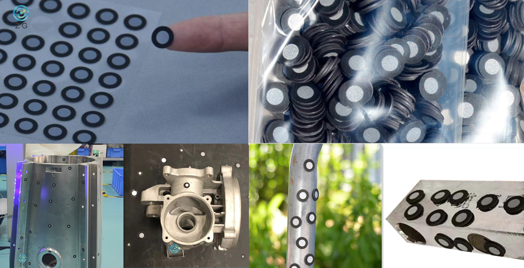 Sticker Reflective Markers Magnetic Reflective Markers
2. Why Are Reflective Markers Needed in 3D Scanning?
3D scanners can be classified according to one of their main features: the positioning method. Laser scanners project multiple laser lines on the object to be scanned, while structured-light (or white-light) scanners project light and shade patterns. Both of them will take images and analyze the projection’s specific deformation on the object to extract 3D data.
The scanning data is displayed in the form of point cloud or triangle mesh. As the scanner moves around the object during scanning, different sets of scanning data are brought into a common coordinate, where data is merged into a complete model. This process is called alignment or registration, it can be done in real-time during the scanning process, or in the post-processing step.
The application of reflective markers solves two separate issues in 3D scanning: Difficulty of Accurate Scanning Data Alignment and Difficulty of Attaining High Accuracy on Large Objects.
2.1 Difficulty of Accurate Scanning Data Alignment
As we know, the structured-light (or white-light) 3D scanners can generate complete 3D surface of an object without using a single reflective marker. It has sophisticated algorithms which will align the scan images data based on geometric features of the object. However, this kind of guesswork doesn’t always lead to great results, and in many cases, especially for objects with large flat surfaces and no unique geometric feature, even the most sophisticated algorithm will fail.
Imagine scanning a steel plate which is 8-meter long and 6-meter wide, there are no geometric features on the steel plate surface at all. Placing reflective markers on the sheet plate surface can give the 3D scanner a “constant feature” to track, which enables the scanning software to register all different scanning frames for the 3D data sets, and align the 3D data sets to form complete 3D scanning data. If without reflective markers, the 3D scanner will lose its alignment and the software will not know how Frame1 is supposed to be aligned to Frame2, Frame2 to Frame3, and so on…
2.2 Difficulty of Attaining High Accuracy on Large Objects
During scanning, when 3D scanner detects reflective markers on the object surface, it enables the scanner to determine its location in space based on relative position to the object, which is called self-positioning or dynamic referencing. While as the scanner moves around the object during scanning, error can accumulate as the scanning volume grows, especially for large objects. It is possible to minimize the accumulation of the error by using technologies such as photogrammetry and reflective markers.
Before scanning, there is a process called pre-modeling to obtain a preliminary skeleton for the object to be scanned. Using a photogrammetry system to take photos of reflective markers on large object surface firstly, the photogrammetry system can triangulate the markers in the images to determine their location in a three-dimensional space. When the markers data is imported into scanning software, it can help to constrain the scan data to generate exceptionally accurate and repeatable 3D data for large objects very quickly.
Kindly check how the PhotoShot Lite Photogrammetry System and reflective markers help ZG 3D scanner RigelScan Plus to conduct precise 3D inspection of 8m x 6m x5m and 5m x 3m x2.5m heavy-duty equipment subassemblies.
3. Reflective Markers Placement Guidance
For markers placement, the operator needs to pay attention to the following points,
3.1 Place Markers on the Object
The reflective markers should cover the whole object surface, try to place the reflective markers on the flat area. If the condition is restricted, place the markers on the less curved area as much as possible. If the markers deform at a large degree, the scanning accuracy will be influenced.
For ZG 3D scanners, at least 4 reflective markers have to be seen in every frame to perform normal 3D scanning. For standard and wide-range scanning, the operator can apply Φ6mm reflective markers and place the markers at the distance of 60mm-100mm between each marker; For specific areas needing ultra-fine scanning, apply Φ3mm reflective markers and place the markers at the distance of 20mm-50mm.
3.2 Place Markers on Object’s Surroundings
When the part is too small or the reflective markers can’t be placed properly on the object surface, markers can be placed around the object's surroundings. For this circumstance, please make sure the relative position of reflective markers and object remains the same during scanning.

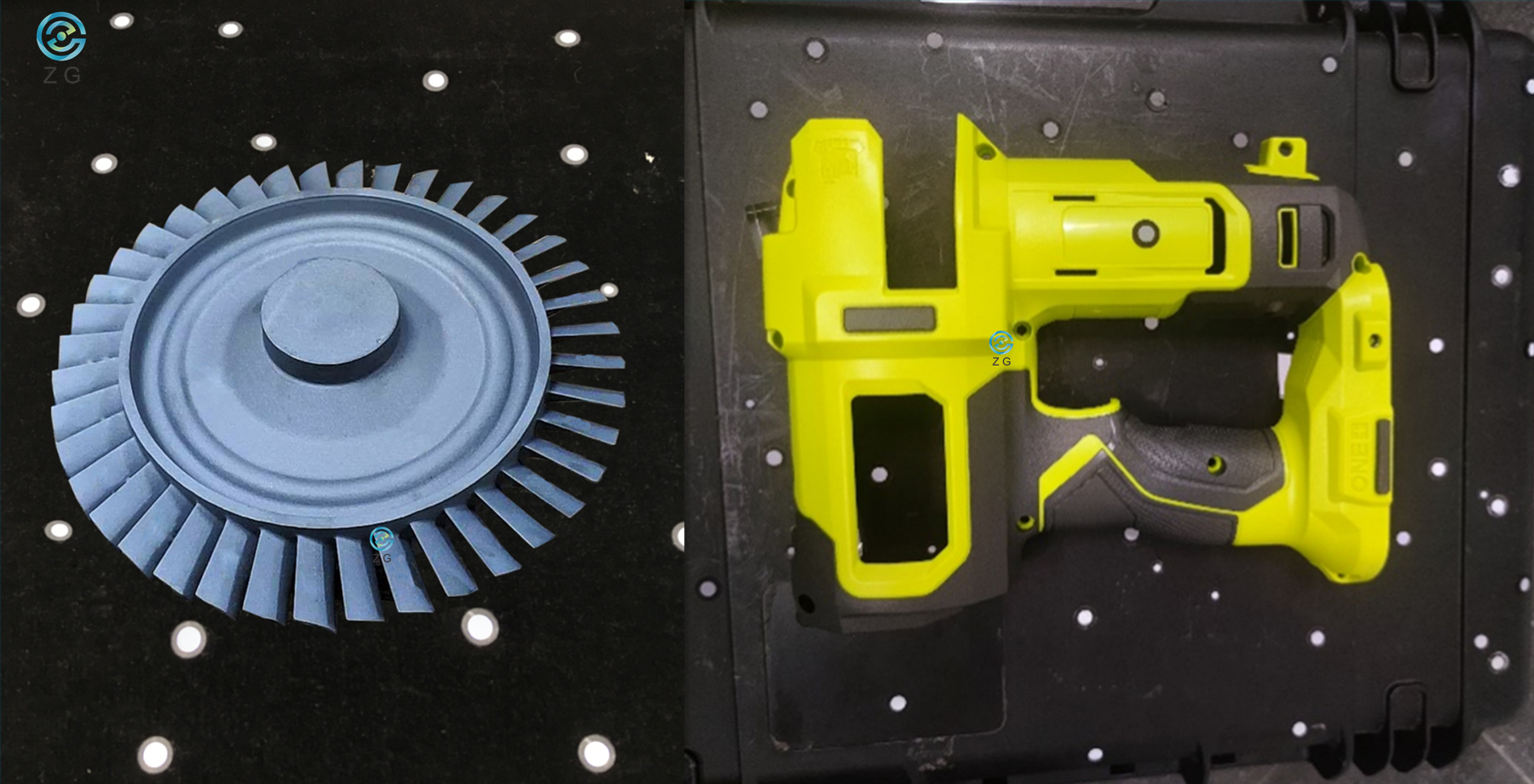
3.3 Reflective Markers Placement Precautions
3.3.1 Do Not place the markers on the surface with high curvature.
3.3.2 Do Not place the markers near the edge/ detail of the object (<4mm).
3.3.3 Do Not place the markers neatly in a line or at equal distance (the 3D scanner cannot perform accurate calculation).
3.3.4 Do Not place the markers in regular forms such as triangles or squares.
3.3.5 Do Not use Damaged, Incomplete, Greasy, or Dirty markers.
The wrong examples are as below,
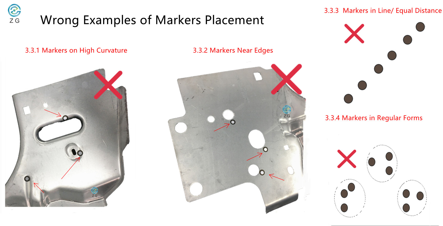
3.4 More to Know
3.4.1 The 3D scanner might sometimes doesn’t see a reflective marker when scanning from a large angle. This means that when scanning around a bending area (like from the front bumper of the car to the back door), try to place more reflective markers in the field of view.
3.4.2 The ZGScan and HyperScan scanning software can display how many markers the 3D scanner is seeing in real-time. If you are not sure about whether you’ve placed enough markers on the object, turn on the scanner and click "Scan Markers" in the scanning software, you will see how many markers the scanner sees in each frame and if more markers are needed.
4. How Can ZG 3D Laser Scanner Help Quality Inspection When Scanning with Markers?
Injection molds need to be maintained strictly on regular basis for essential refurbishing so that they can keep performing at the dimensions and accuracy as originally designed.
With multi-mode, versatile metrology-grade 3D scanner -- AtlaScan, we can scan the markers on the mold first to get an overall shape of the entire mold and the markers spatial data, which we can import into the scanning software and scan the surface of the mold. During the surface scanning process, the scan data will be automatically aligned to the imported markers data, the scanning data is tightly constrained and extremely accurate. Then the 3D scanning data is compared with original CAD model to generate 3D color map and inspection report, the engineers can know if the mold needs refurbishing or not clearly.

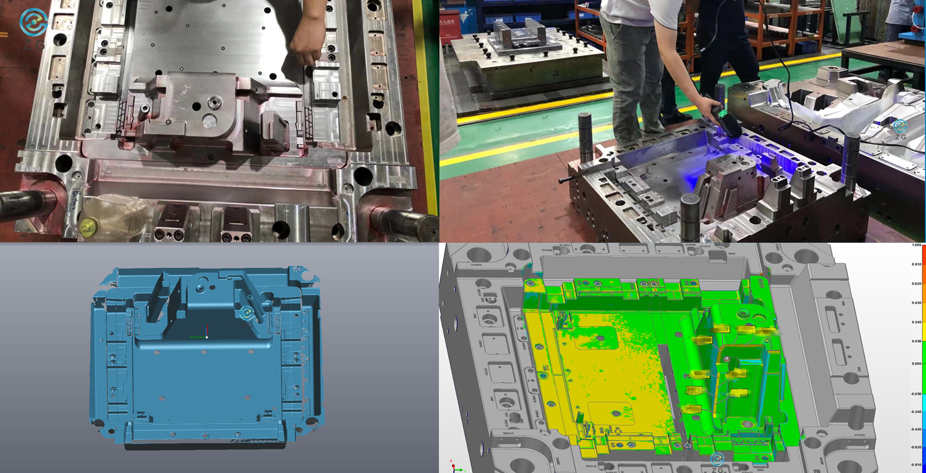
AtlaScan- Scan with Reflective Markers for Mold Inspection
The specific process is as below,
1. Place enough reflective markers properly on the mold surface.
2. Connect AtlaScan with power and warm up the scanner for 20mins.
3. Click "Scan Markers " in ZGScan software, capture all the markers on mold surface, and export markers data.
4. Click"Import Markers" to import the markers data into ZGScan software.
5. Click"Scan Surface"and start scanning the mold surface.
6. Process the scan data and save it in the format of .stl.
7. Import the scan data into 3rd party software to generate 3D color map and inspection report.
For more information about ZG professional metrology-grade 3D laser scanner AtlaScan, please check ZG professional metrology-grade 3D laser scanner AtlaScan.
5. Marker-Free Solutions
During daily communications with customers, we have received many different iterations of the same question over and over. Something along the lines of: “Do we have to place markers on the part?” or “Is there any way can save us the time of placing markers on the object surface?”. Reflective markers benefit fast and accurate 3D scanning, while sometimes the markers placement does increase the setup time and limit the size of objects that can be scanned efficiently.
As ZG Technology continues to improve our high-quality products, the two Marker-Free scanning systems below can help the users to save the time of placing markers on object surface and increase scanning efficiency dramatically.
5.1 HyperScan Optical Tracking 3D Laser Scanner

Smart Optical Tracking 3D Scanner, HyperScan, adopts blue laser technology with multiple working modes. The hardware of HyperScan is composed of an optical tracker and a handheld 3D laser scanner with a rigid structure marker frame. During the scanning process, the optical tracker will track the markers on the scanner and establish the scanner’s position in the space. Thus there is no need to place positioning markers on the measured workpiece, which not only improves the convenience of operating the handheld scanner but also truly realizes instant scanning at the scanning site.
5.2 MarvelScan Tracker-Free & Marker-Free 3D Laser Scanner
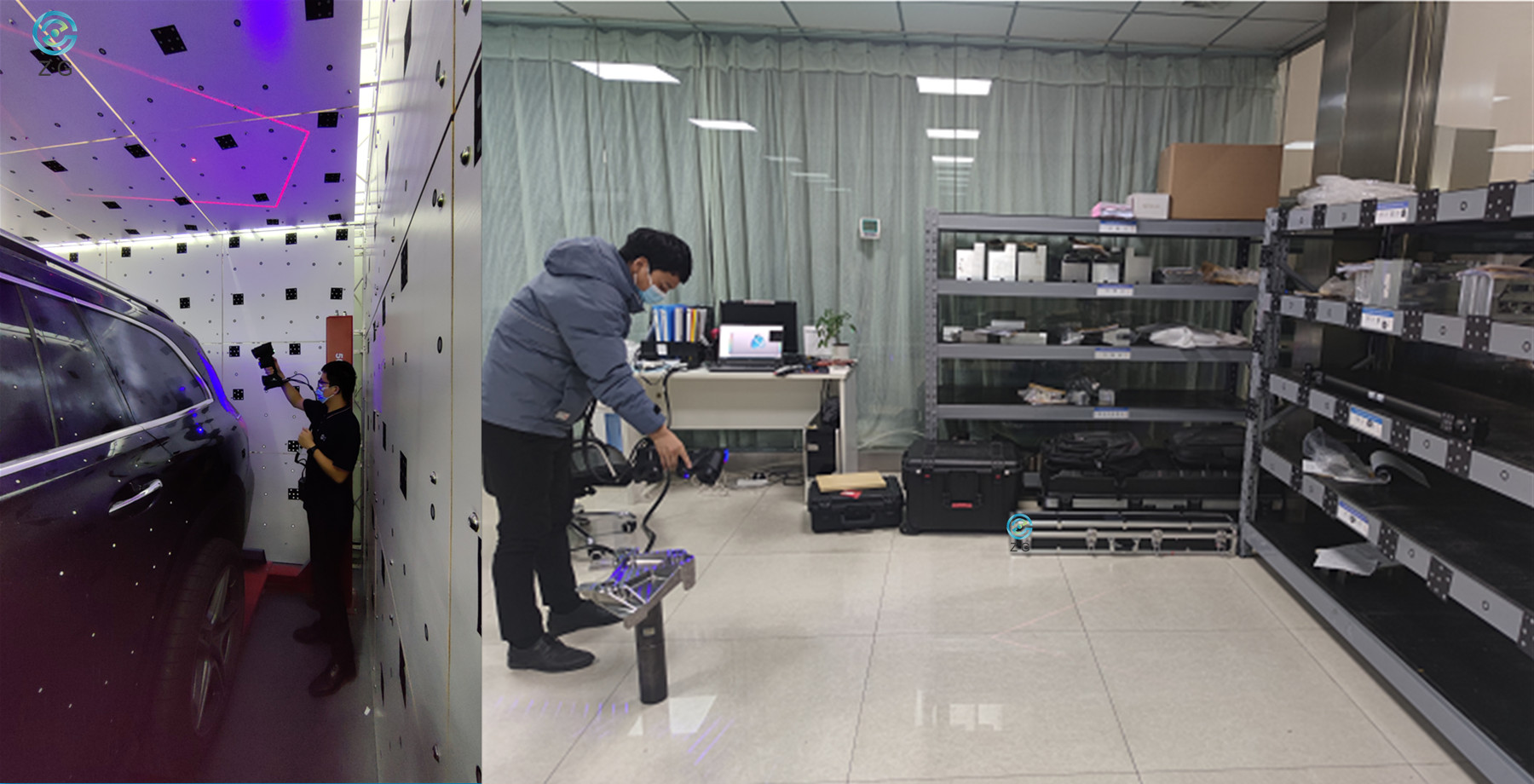
MarvelScan, the first Tracker-free and marker-free portable 3D laser scanner in the world, is a breakthrough product to change the working method of a portable 3D laser scanner with faster scanning efficiency. Thanks to the unique Inside-Out monocular positioning technology, during the whole scanning procedure, the operator does not need to place sticker markers at all. Compared to other optical tracking scanning system, MarvelScan does not require a rigid structure with markers around the scanner or an optical tracker at all, which improves portability and simplify the calibration procedure dramatically.
6. The Conclusion
With the help of reflective markers, 3D scanners are more and more used to get complete or partial 3D measurements of any physical object. 3D scanners can generate millions of points per second, the measurement and inspection efficiency are much higher when compared to traditional “point-by-point” measurement devices. Meanwhile, ZG Technology also offers Marker-Free solutions that the operators don’t need to place markers on object surface at all. If you have any other questions about reflective markers or ZG 3D scanning solutions, please feel free to contact ZG Technology for further discussions.


